
 EN
EN
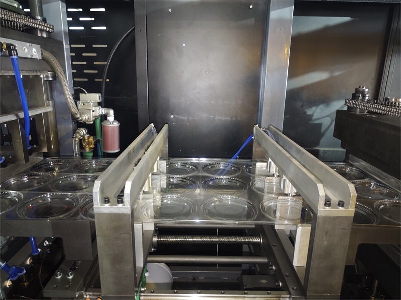
فهم مطابقة معدات القص الدقيقة بالقالب
لماذا تؤدي محطات القص غير المُحاذاة بدقة إلى نسبة هدر تفوق ٢٣٪ في التشكيل الحراري عالي الإنتاجية
عدم التوافق بين القالب وسرير المحطة الميكانيكية للقطع يُعَدُّ سببًا رئيسيًّا لإهدار المواد. فعندما ينحرف أداة القطع بمقدار ٠٫٢ مم فقط، تتمزَّق المادة الرقيقة بدل أن تُقطَع بدقةٍ نظيفةٍ، ما يؤدي إلى حواف غير منتظمة وأجزاء غير مكتملة. وفي التشكيل الحراري عالي السرعة، قد يؤدي انحراف دورة واحدة فقط إلى رفض جميع الأجزاء المنتجة في تلك الدفعة. وقد أكدت دراسة كفاءة الإنتاج لعام ٢٠٢٤ أن سوء التوافق يسهم مباشرةً في معدلات الهدر التي تتجاوز ٢٣٪ في العمليات عالية الحجم. ومن الأسباب الجذرية لذلك: اهتراء المحامل، والتمدُّد الحراري لإطار الآلة، وعدم الاتساق في إعداد النظام أثناء التغييرات بين المهام. أما استعادة الدقة فيتطلَّب قياس المسافات بين القالب والسطح المقابل باستخدام الليزر، وضبط السلسلة الحركية للمحطة بدقة للحفاظ على التوازي تحت الأحمال المتغيرة.
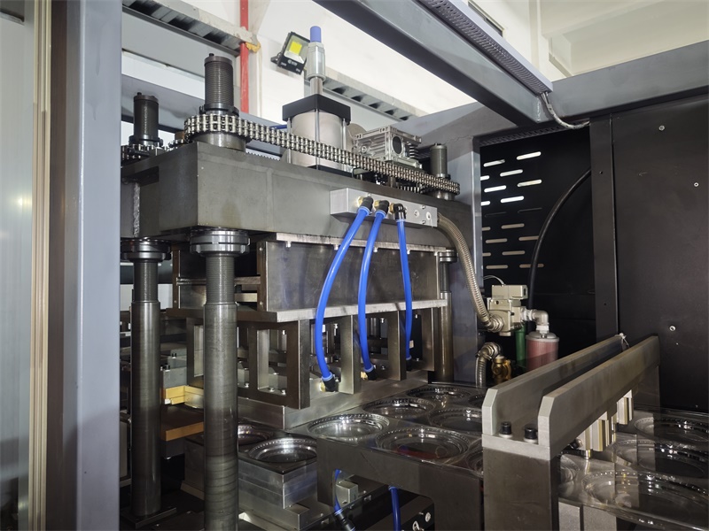
إطار المطابقة الثلاثي النقطي: تحمل الأدوات، حركيات الآلة، وتعويض الانثناء العائد للمادة
تحقيق دقة موثوقة في محطة قص القوالب يتطلب تقييمًا منهجيًّا لثلاثة عوامل مترابطة بشكل وثيق.
- تسامح الأدوات – يجب أن يظل حافة القطع حادة، ويجب أن يبقى الفراغ بين القالب ولوحة التقابل ضمن النطاق ٠٫٠٥–٠٫١٢ مم للدرجات الشائعة المستخدمة في التشكيل الحراري. إن ضيق الفراغ أكثر من اللازم يُسرّع التآكل، بينما يؤدي اتساعه الزائد إلى تورُّم الحواف وقص غير كامل.
- حركية الماكينة – يجب أن تكون حركة اللوح أو الأسطوانة الدوارة سلسة وقابلة للتكرار. وتضمن المحركات الخدمية الكهربائية ذات التغذية الراجعة المغلقة ثبات السرعة والمحاذاة، مع تعويض تأثير القصور الذاتي ومرونة هيكل الماكينة. بل إن أي انحراف زاوي طفيف يُغيّر مسار القالب، ما يؤدي إلى انزياح المثقاب وتمدد المادة.
- تعويض ارتداد المادة الأجزاء الحرارية غالباً ما تعود إلى الوراء بعد تشكيلها، وتغير موقعها قبل القطع. توقيت التكيف أو ملفات تعريف الضغط تتوقع هذا السلوك: بالنسبة لـ PETG أو البولي بروبيلين ، فإن عمق الزيادة القليلة أو وقت البقاء المتحكم به يُحيد الارتداد البعدي ويحافظ على دقة خط التقطيع.
عندما يتم تحديد هذه العناصر الثلاثة، يزيل المشغلون الأسباب الجذرية للفشل في التحديد ويظلون باستمرار أقل من عتبة 23٪ من الخردة.
كيفية اختيار القطع المقطوعة بناء على متطلبات الجزء ومستوى الإنتاج
إدراجات متكيفة معدة بالإنترنت مقابل محطات هندسية ثابتة للتشكيل الحراري متعدد المواد
محطة قطع الديرو معدات قطع الدقة مطابقة المفاصل على كيفية التعامل مع مختلف الركائز. بالنسبة للتشكيل الحراري متعدد المواد ، توفر الإدراجات المعدلة بالعدد الآلي التكيفية مرونةً وحداتيةالانتقال من ABS الصلب إلى الإيلستومرات الحرارية الناعمة يستغرق دقائق ، وليس ساعات. تُعد المواد الهندسية الثابتة، في حين أنها فعالة من حيث التكلفة في أحجام عالية جداً ومخصصة، تعاني من الارتداد المادي المتغير: يمكن أن يؤدي تحول 10٪ في استعادة المرونة إلى تدهور النهاية الحافة. كما وجد معهد التعبئة والتغليف المرن (2023) ، فإن العمليات التي تعمل بثلاثة أسر مواد أو أكثر توفر 18٪ في وقت التغيير باستخدام أنظمة قائمة على الإدراج. عندما تتغير هندسية الجزء أسبوعياً، فإن الأدوات التكيفية تمنع ارتفاعات الخردة وتحافظ على الإنتاج دون عبء رأس المال من مجموعة متعددة من المصفوفات المخصصة.
مصفوفة القرار: مواءمة اختيار القطع المقطوع مع تحمل GD&T (± 0.15 ملم) ، وقت الدورة (< 8 ثانية) ، والحجم السنوي (> 500k وحدات)
يجب أن يحقق قاطع القوالب المناسب جميع القيود الثلاثة في وقت واحد. ويجري الجدول أدناه تعيين أنواع قواطع القوالب الشائعة مقابل هذه الحدود.
| نوع قاطع القوالب | تسامح هندسة الأشكال والأبعاد (±٠,١٥ مم) | زمن الدورة (<٨ ثوانٍ) | الحجم السنوي (>٥٠٠ ألف وحدة) |
|---|---|---|---|
| قاطع قوالب مستوي (هيدروليكي) | يمكن تحقيقه باستخدام أدوات صلبة، لكن قد يطرأ عليه انحراف خلال التشغيل عالي الحجم لفترات طويلة | متوسط زمن الدورة ١٠–١٢ ثانية، وهو بطيء جدًّا بالنسبة للمتطلَّب | مناسب فقط مع التحميل الآلي؛ وكفاءته عند التصنيع على نطاق واسع تكون هامشية |
| قاطع قوالب دوار (محرك سيرفو) | الثبات المتسق عند التحكم في درجة حرارة الشبكة—لكن الانحراف الناتج عن الحرارة في بولي بروبيلين رقيق قد يتجاوز ٠٫٢ مم | أقل من ٦ ثوانٍ بسهولة، ضمن الحد المستهدف وبشكل جيد | الأفضل لعدد وحدات يفوق المليون؛ وتغيير القالب السريع يضمن استمرارية الإنتاج العالي |
| منقور باستخدام ماكينة تحكم رقمي حاسوبي (إدخال تكيفي) | يحافظ على دقة ±٠٫١٠ مم عبر مواد متنوعة بواسطة خوارزميات تعويض فورية | ٧–٩ ثوانٍ، قرب الحد الأقصى؛ ويستلزم تحسين ترتيب القطع | يتفوق في الإنتاج متوسط إلى عالي الحجم مع تبديل المهام المتكرر—ويجنب الازدواجية الرأسمالية المكلفة |
لعدد وحدات يفوق ٥٠٠ ألف، وزمن دورة أقل من ٨ ثوانٍ، وتحمل هندسي دقيق ±٠٫١٥ مم، تُعدّ آلة الطبع الدوّارة ذات القيادة الكهربائية الخيار الرئيسي—بشرط أن تكون سماكة المادة واستقرارها الحراري متسقَيْن. وعندما يتغير مزيج القطع شهريًّا، تجنب الأنظمة التكيفية القائمة على التحكم الرقمي الحاسوبي الهدر الاقتصادي عبر إلغاء تكاليف إعادة تجهيز القوالب الثابتة. ويجب أن يراعي الاختيار التوازن بين قدرة زمن الدورة ومخاطر عدم الالتزام بالمواصفات—وخاصةً في بولي بروبيلين رقيق، حيث قد يستدعي الانجراف الحراري استخدام بديل أبطأ من نوع الطابعات المسطحة.
آلات قص الألواح المسطحة والدائرية والمُبرمَجة باستخدام الحاسوب: التنازلات الأداء في عملية التشكيل الحراري
عندما تفشل أدوات القص الدائرية في أداء مهامها على البولي بروبيلين ذي السماكة الصغيرة بسبب انحراف الشريط الناتج عن الحرارة
يتفاعل البولي بروبيلين ذو السماكة الصغيرة (PP) بشكل ضعيف مع الاحتكاك المستمر المتأصل في عمليات التحويل الدائري. وتولِّد السكاكين الأسطوانية حرارةً موضعيةً، ما يؤدي إلى امتداد الشريط ذي نقطة الانصهار المنخفضة وانحرافه — مما يُخلّ بالتسجيل الدقيق حتى عند تحقيق محاذاة أولية مثالية. ويؤدي هذا الانحراف الحراري مباشرةً إلى إعاقة دقة معدات القص في محطات القص، ما يُفقِد التوافق بينها. وتُظهر الأدلة الصناعية أن هذه الظاهرة ترفع معدل الهدر إلى ما يتجاوز ٢٣٪ في عمليات التشكيل الحراري عالية الإنتاجية (٢٠٢٤). أما بالنسبة للبولي بروبيلين ذي السماكة الصغيرة، فإن محطات القص المسطحة أو تلك المُبرمَجة باستخدام الحاسوب — حيث يبقى اللوح ثابتًا أثناء القص — تتفادى تمامًا عدم الاستقرار الناتج عن الحرارة، ما يحافظ على الدقة الأبعادية وجودة القص.
التحقق من تكامل محطة قص القوالب: المعايرة، الاختبار، وقياس العائد على الاستثمار
يتطلب تأمين العائد على الاستثمار في نظام قص القوالب إجراء اختبارات تحقق دقيقة. فبدون التكامل السليم، حتى المعدات عالية الدقة التي تتطابق مع المواصفات تفشل—مما يؤدي إلى الهدر وتآكل الهوامش. ويُشكّل المعايرة الأساس: فهي تُوحّد تحملات الأدوات، وتثبّت حركة الآلة، وتعوّض انعكاس المادة المستخدمة—مما يقلل العيوب مباشرةً ويمنع توقف التشغيل غير المخطط له.
ويجب أن تتجاوز اختبارات التحقق الوظائف الأساسية. قِس معدل الإنتاج الابتدائي، ووقت الإعداد، ومعدل النفايات، ومدخلات العمالة. قبل بعد المعايرة، راقب نفس المؤشرات لقياس مدى التحسّن. فتخفيض نسبة النفايات من ٢٣٪ إلى أقل من ٥٪ وحده كافٍ لتبرير الاستثمار خلال أشهر. ويُحسب العائد على الاستثمار بمقارنة إجمالي تكلفة الملكية—وتشمل المعدات والصيانة وتوقف التشغيل—مع التوفير الناتج عن خفض الهدر، وتسريع عمليات التغيير، وزيادة الإنتاج. أما المصنّعون الذكيون فيعاملون المعايرة ليس كنفقة، بل كأداة لحماية الربح، مرتبطًا كل ميكرون من الدقة مباشرةً بالنتيجة النهائية.
الأسئلة الشائعة
ما السبب في عدم انتظام محطة القص بالقالب؟
يحدث عدم انتظام محطة القص بالقالب عادةً بسبب تآكل المحامل، أو التمدد الحراري لإطار المكبس، أو عدم الاتساق في الإعداد أثناء عمليات التغيير، ما يؤدي إلى ارتفاع معدلات الهدر.
ما الغرض من إطار التطابق ذي الثلاث نقاط؟
يقيّم إطار التطابق ذي الثلاث نقاط تحمل الأدوات، وحركية الماكينة، وتعويض ارتداد المادة الأساسية لضمان قص دقيق وموثوق بالقالب.
ما نوع قاطع القوالب الموصى به للإنتاج عالي الحجم؟
عادةً ما يكون المكبس الدوراني الذي يُدار بواسطة محرك سيرفو هو الخيار الأمثل للإنتاج عالي الحجم، نظراً لسرعته العالية في دورات التشغيل، ودقته العالية في التحملات، وثبات نتائجه.
كيف يمكن التخفيف من الانجراف الحراري في قواطع القوالب الدورانية؟
يمكن أن تساعد محطات القص المسطحة أو تلك المصنوعة باستخدام آلات التحكم الرقمي (CNC) في تجنّب مشاكل الانجراف الحراري، لا سيما عند معالجة البولي بروبيلين رقيق السمك الحساس للحرارة.
لماذا تُعد الاختبارات التحققية ضرورية بعد المعايرة؟
تُقَيِّم فحوصات التحقُّق التحسينات في معدل الإنتاج ونسبة الهدر ووقت التوقُّف بعد المعايرة، مما يضمن عائد الاستثمار في نظام القص بالقالب.
جدول المحتويات
- فهم مطابقة معدات القص الدقيقة بالقالب
- كيفية اختيار القطع المقطوعة بناء على متطلبات الجزء ومستوى الإنتاج
- آلات قص الألواح المسطحة والدائرية والمُبرمَجة باستخدام الحاسوب: التنازلات الأداء في عملية التشكيل الحراري
- التحقق من تكامل محطة قص القوالب: المعايرة، الاختبار، وقياس العائد على الاستثمار
- الأسئلة الشائعة